Unless you’ve been living under a rock for the last 20 years, it should come at no surprise that the world has becomes more and more connected! Everything is smart this, smart that, cloud, buzzwords…ahhhhhhh! This connected world means connected systems in the building space, new expectations, and new skills to learn!
You might be thinking, “I’m not in IT, why do I need to learn networking”? Well, let me tell you why.
If you’re even tangentially involved with building automation systems (BAS), there’s something to be gained by better understanding how networks work. This obviously pertains to the people installing the BAS and those integrating with them, but it also extends to commissioning agents, and operators who simply want to access the BAS. The great thing is that the fundamentals you learn extend beyond BAS and can be applied to your home and cloud connected systems.
There are many complicated things in life that get boiled down to a model. It’s important to remember that a model isn’t exact, but a simplified representation of what is being modeled. At times, the line between models layers can be blurry, so focus on understanding the major concepts that these layers attempt to separate and don’t get stuck on the minor details (at least not now). We’re trying to gain a high level understanding of network communication, the problems that need to be solved, and not picking a side in an online holy war.
For networking we have two models: 1) The 7 Layer OSI Model and 2) the 4 Layer TCP/IP Model. The TCP/IP model is a simplified model that for most people is of sufficient complexity to explain networking. However, I’ll be using the 7 layer OSI model as the separation of roles and concepts will be important as we’re getting into the nitty gritty of networks and not just plugging in a network cable and hoping for internet magic to happen.
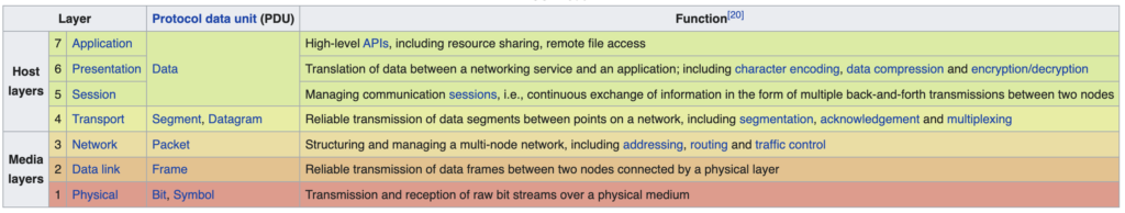
Above, is a nice summary table of the OSI model from Wikipedia. We’ll start from the bottom and explain it with BAS examples. If you’re a control contractor/systems integrator or someone responsible for the physical networking, then you’re going to want to pay extra attention to the bottom four layers of the model which are the focus of this post.
Layer 1 – Physical
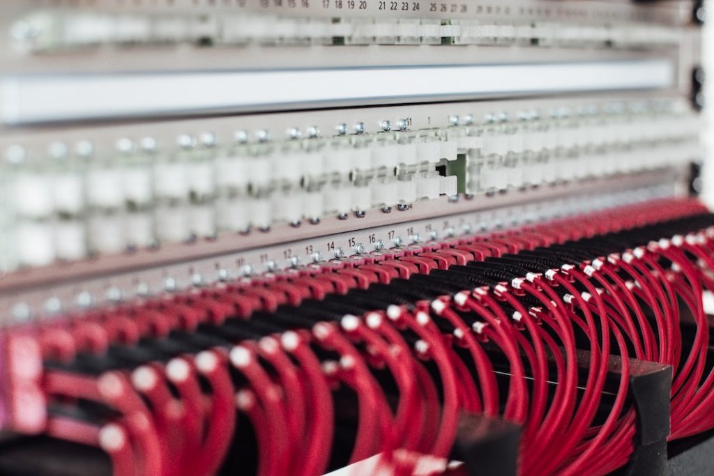
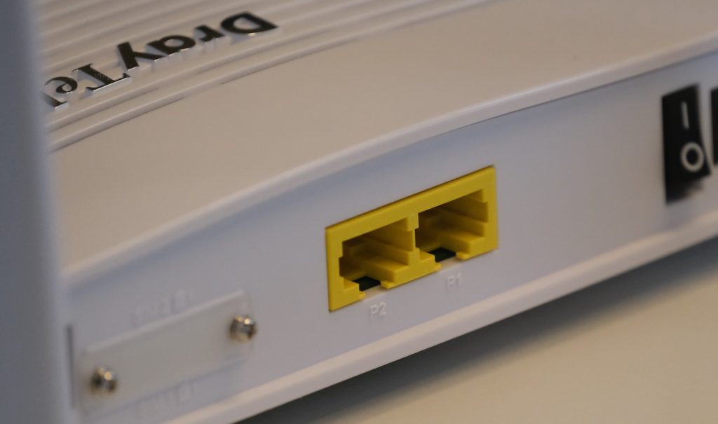
As the name implies, the physical layer has to do with physical interfaces and specifications of your network. The main thing to keep in mind, is that this has to do with the transmission of raw bits over a medium. If I have two devices directly connected, how is information communicated? Digital signals are transmitted as zeros and ones. There’s either enough voltage on the line to be interpreted as one or the lack of voltage is interpreted as a zero. This lays down the infrastructure for doing so. We’re not necessarily concerned with where the signals need to go or making sense of the message (that’s the responsibility of other layers), but just making sure electrical signals get from A to B. This includes your cable, the connectors on the ends, and the sockets they go into. For a network of computers we’re talking about things like CAT-5E/6A, the RJ-45 connectors, and the physical aspect of network cards. In a BAS system, this is your RS/EIA-485/232 specifications that govern the drivers and receivers of your serial networks (i.e. BACnet MSTP).
This also includes the concept of half-duplex vs. full-duplex. If you think of wires as a highway of electrons, it makes sense that there needs to be some order for electrons to can get from source to destination reliably and without crashing. Half-duplex means that when two devices are connected, only one can speak at a time. If you have a single piece of copper connecting two devices, it makes sense that only one of the devices can put voltage on the line at a time without there being an electron “car wreck”. The protocol most of us are familiar with is BACnet MSTP which uses two copper wires to get a voltage difference to determine ones and zeros. This physical limitation in the protocol results in half-duplex communication as only one BACnet master device can speak at a time. Conversely, “ethernet cables” have multiple pairs of copper, dedicated transmitting and receiving cables, and allows for bi-directional communication.
Hubs are layer 1 devices. They receive messages on one of their ports and “broadcast” that message on all of their remaining ports indiscriminately. As you can imagine this is incredibly inefficient. Physical data lines are kept busy with messages that may or not be meant for the device on its port. This problem is addressed at the next layer.
Layer 2 – Data Link
Our next layer is the data link layer. In the previous layer we focused on two devices, directly connected, and sending raw bits to each other. In this next layer we need to solve the problem of communicating to devices that are on the same local network but not directly connected to each other. If you are sending files across your network at home, this is exactly what we’re speaking of.
With more than two devices, addressing becomes a thing. You can’t rely on sending a bit down the line and know that it’s going to exactly where you need it to go. If you’re in a small apartment complex, you still need a way to uniquely identify apartments even if it’s as simple as an apartment number. In the layer 2 world, we have the MAC address. The MAC address comes from the factory and is unique to each network interfacing port. If you have an ethernet port and a WiFi card, they will have different MAC addresses.
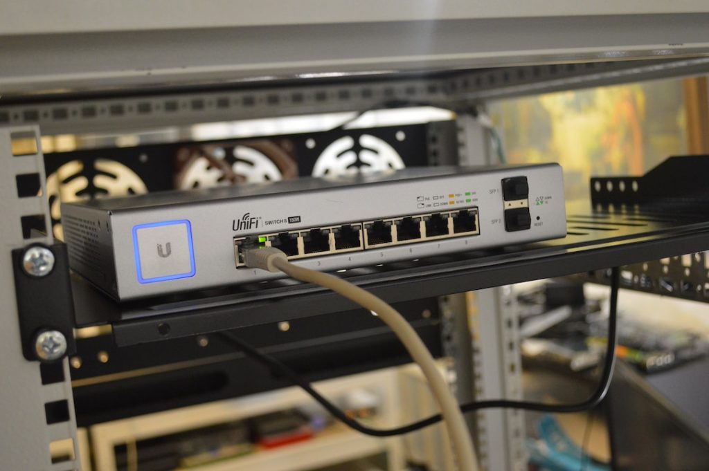
The layer 2 equivalent of the Hub is the network switch. A switch is a more sophisticated hub that allows for greater speeds by not sending duplicate messages to devices that don’t need it. It does this by maintaining a MAC address table. Effectively this is a lookup table. The network switch is able to interrogate the network and create a table with one column containing the MAC address of devices on the network and the second column saying what port the message should go out of to get to that MAC address. So when you send an ethernet frame containing your message and the MAC address of where your message needs to go, the network switch(es) check their MAC address table and send the message out the proper port(s).
Let’s bring this back to the BAS. It should be no surprise that BAS network architecture significantly lags their commercial counterpart. However, it’s important to understand the problems being solved and the common techniques being used by each.
Your BACnet MSTP bus (and any of your serial buses) combine concepts from Layer 1 and Layer 2. Your MSTP wire is “dasiy-chained”, so the red wire one side of the network bus is electrically connected to the red wire at the end of the bus. Same thing with the black wire. If you think to the above scenario, that means that this has to be half-duplex communication as when any one device talks, it ends up hogging the line until it hangs up. This communication is largely Layer 1 as there is no switch directing traffic, however the concept of a MAC address does exist. A MAC address in the network world is a Layer 2 concept. So while we’re blasting the entire network bus with a common message, only the device with the MAC address corresponding to the message will act on on it.
Before ending this section, Layer 2 communication is not confined to serial buses. BACnet ethernet, while quite rare in modern deployments, is still a thing. Multiple BACnet devices with ethernet ports can communicate to each other without dedicated IP addresses. They simply send messages address to each other’s MAC address and allow the network switch(es) to make the proper decisions to get the message to their destinations.
Layer 3 – Network
The network layer addresses the next logical problem… how do I get messages outside of my network? Layer 1 addressed how two devices physically connected can communicate. Layer 2 provided an addressing scheme to allow devices on a local network to communicate. Layer 3 will allow a device from one network to communicate with a device on another network. This layer introduces the concept of IP addresses and routing.
While a MAC address is a physical address assigned from the factory, an IP address is a logical construct. You can change the IP address assigned to a network interface very easily. You can even assign multiple IP addresses to a single interface. IP addresses need only be unique within their network. You and I can both have the same IP address scheme within our homes as our homes are on separate networks. We won’t cover the concept of NAT here but the ability to logically assign addresses is key to how modern systems are maintained.
Routers perform a similar role as switches, but now between networks and with IP addresses. They do this by maintaining an ARP table. ARP stands for address resolution protocol and is beyond the scope of what we’re trying to cover. However, at a high level ARP is another lookup table containing the MAC address of devices and their IP addresses.
One of the key decisions made by your computer is determining if an address is local or on a different network. If it’s local, then it will send it locally and allow switches to get the message where it needs to go. If it’s not local, then it send the message to the default gateway (i.e. the router). The router is then in charge of “routing” the message to other routers until it gets to the network containing the destination at which point layer 2 protocols are responsible for getting it the rest of the way. In the mail example, when the IP addresses is not in your apartment complex, you take it to the post office with a detailed address and through their sophisticated network it gets to it’s destination.
Bringing this back to building automation, these are where most of your higher level protocols reside. Your BACnet IP, Modbus TCP/IP, Niagara’s Fox Protocol, etc. BACnet IP is a bit special in that it’s not routable in the typical sense and if you want devices to communicate, they should be on the same VLAN. We’ll touch upon a bit in the next layer but the rabbit holes are deep and plenty and we have a lot to cover, so onward we go!
Layer 4- Transport

In layer 4 we now move away from the addressing side of networking and onto establishing a connection and make the magic happen! There are two big details that happen at this level as far aw we’re concerned; 1) Ports and 2) TCP vs. UDP.
Okay, I fibbed a bit about addressing being over. If your IP addressing contains all the information for your buddy to send a parcel to your home, the port is the recipient of the parcel. Computers are complicated devices that are providing or utilizing multiple web services at any given time. If your computer is running a web site, a BAS software with a web server, an analytics web server, a reverse proxy server, and so on and so forth, you need to make sure they’re running on different ports. If I want to go to your analytics service, then I need to uniquely identify the service I wish to speak to with the port number. It’s very much akin to going to one of those office buildings with multiple small businesses sharing a space and saying I want to speak to Business A who are in Room 80 to differentiate from all the other businesses cohabitating the same address.
Those most popular ports are 80/443 which which are the default ports for http/s. Most web services run on these ports by default. If you want to run multiple web services, you’ll need to assign them to different ports. Ports are noted by a colon after the ip address followed by the port number. For example, 127.0.0.1:81. When you put an ip address or website name in your browser it defaults to 80/443 because that’s what’s expected. BACnet, Modbus, Fox(s), all have default ports for their communication.
The second major concept handled at this layer is TCP vs. UDP. The acronym names don’t really matter as much as their philosophical differences. UDP is a “connectionless” protocol. It’s “fire and forget”. If I’m the quarterback throwing bombs to my receiver, I don’t wait to see if he caught the ball, I just keep bombing away. As you can imagine, there’s very little overhead here and I can get a lot of footballs thrown but not necessarily caught.
TCP is a “connection-oriented” protocol. It is used for reliability, where it is very important that the message gets to the recipient before you make the next throw. If the message fails to be received, you go back and do it again. This has quite a bit of overhead as you can imagine, especially compared to UDP but it is how the bulk of our communication is handled. TCP has something called the “3-way TCP handshake” that is used to initiate a session. Once again, we will resist the urge to go down this rabbit hole and move on. But very quickly, BACnet is UDP and relies heavily on broadcasts which can not leave the network. Protocols like Niagara’s Fox(s) is TCP and better suited for routing and to be used across larger networks.
Conclusion
In summary, the bottom four layers of the OSI model are fundamental to data communication. These layers cover how we physically interconnect systems, address senders/recipients, and get messages from one to the other. Most troubleshooting in the BAS/system integration world occurs at these layers. Whether it’s in a new cable run (i.e. CAT-6A or MSTP cabling), setting up a new network, or integrating systems, understanding these layers of the OSI model greatly improved your ability to determine the problem and ideally the solution!
We’ll keep layers 5-7 for another day… while important, unless you’re a developer, there’s just a lot less troubleshooting and problem solving ability you will gain from this knowledge.